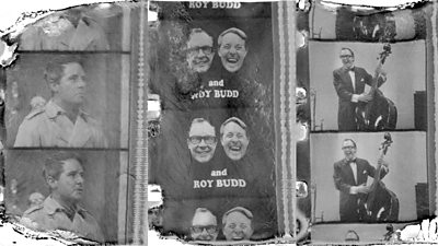
Hopefully you've been following our of about efforts to recover an episode of Morecambe and Wise's first ����tv TV series from 1968. Previously considered 'lost', a badly deteriorating copy of one programme had been found - but was in such bad condition it couldn't be unwrapped from the film reel...
The story now arrives at ����tv Research and Development, and our Adam Wiewiorka explains how, when presented with a set of images that were warped, damaged and - because it was lasered into sections with each chunk of tape containing multiple layers of small sections of film - in no continuous order, he set about trying to develop an algorithm to tackle these challenges.
In October 2015 my former colleague John Zubrzycki invited Charles Norton and Graham Davies to ����tv R&D to present their work on the Morecambe and Wise film recovery at one of our team meetings. At the time all the CT scans had already been performed and work to extract video footage from the scans had begun. However, the poor physical state of the scanned film caused some of the scan data to be difficult to interpret. Layers of film had to be manually identified by viewing the scan slices and marking the image carrying voxels (3D pixels). As each scan contained some 2000 files and more than 100 layers of film, progress was slow and the work was tedious. Having seen Charles and Graham's presentation I approached John with the ‘obvious’ comment: “Surely, large amounts of data should be processed by software”, to which he replied: “Have you just volunteered then?”
About a month later, data from a single scan was sent to ����tv R&D, at which point it became apparent that developing an algorithm for automated processing would present a challenge. A quick look at some cross-sections revealed a number of interesting features such as curvature in all directions, air gaps, areas filled with fluids of various density, cracks and distortions of the image, burn marks from laser cutting, discontinuities at perforations holes and so on.
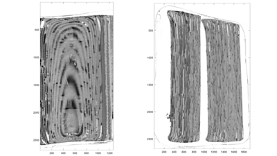
It was obvious that an attempt to identify image layers based on voxel values would be unreliable. A dark patch could just be where the film had turned to goo, whereas a light area was often an air gap in the reel. There were also areas of ambiguity, usually mid-grey, where it would be difficult to follow the correct trajectory even by a human. After some more visual inspection and statistical analysis it became clear that a better policy would be to identify the single feature that is common to all the layers, that is the mid-grey plastic backing of the film, rather than the image.
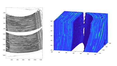
Ideally, this plastic layer should have a constant voxel value, i.e. zero variance. Therefore, if we defined some small surface, e.g. a 30x30 square, we could fit it inside the plastic by moving it up and down and trying different angles until minimum voxel variance were found. This procedure yields a 3D spatial coordinate as well as the elevation and azimuth angles that describe the deflection of the normal to the surface from the vertical axis.
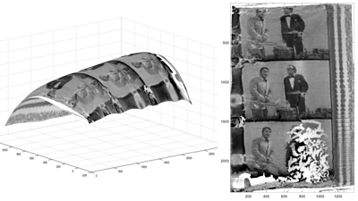
Knowing the angles is important because the location of neighbouring points, also entirely within the plastic layer could be estimated. Starting somewhere in the middle of a layer, a grid of points defining the curvature of the entire layer could be determined. The image layer would then be found by moving along the normal vectors towards the surface of the layer where the variance should be a lot greater and voxel values take arbitrary values from white to full black. Then another layer of plastic would follow, usually with a similar shape to the previous one, barring air gaps or perforations holes.
Although the above approach led to some early promising results, it proved to be unreliable. Apart from features such as perforation holes that introduced discontinuities in the analysed surfaces, the scan data itself turned out to contain imperfections. The most serious of them stemmed from the fact that the scanning process took a long time, up to 24 hours. In some cases, a small temperature change or some other factor caused the sample to move resulting in an ‘echo’ image of up to 10 voxels away from the original position. This usually occurred near the edge of the sample, especially in areas with large curvature. Other problems were caused by ‘shadows’ cast by large dark regions as well as ‘crosstalk’ that would make the mid-grey plastic considerably darker in the vicinity of black image voxels.
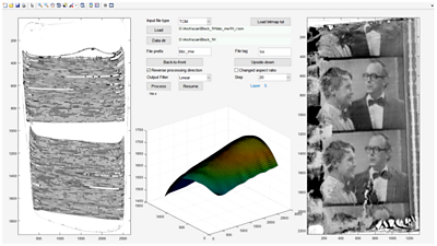
As the work progressed, a number of radical measures had to be employed to address the above problems, as well as countless “corner cases”. For example, a special type of Viterbi decoder was designed to determine the layer structure along the normal vector to the analysed surface. Apart from the obvious “image and “plastic” layers, it also detected “air”, “black” and “goo” areas. Looking at more than one layer helped avoid “jumping” to the neighbouring layer due to some ambiguity or discontinuity in the scan data. Smoothing was achieved by using function fitting, frequency domain filtering, statistical filtering, such as the median filter, and morphological opening and closing filters. A simple graphical user interface was also designed.
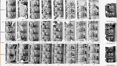
All 37 scan files were processed and over 5000 image files were produced. At this point a new problem emerged. The scanned blocks of film taken from the reel each contained different number of layers of film. They started and ended at different points and, despite all the complexity of the processing algorithm, some layers, especially those at the start of the reel and at the air gaps, were unrecoverable. This meant that the image files from neighbouring blocks were not correctly aligned to form a time sequence - for example file 71 from block C had to be followed by file 67 from block D to form the correct sequence of frames. Again, a piece of software was required to enable easy alignment of the image files. This time a Python script was written that displayed a large number of files in thumbnail form and allowed manual alignment, removal as well as insertion of dummy placeholder files.
The script also generated a text file with the mapping of filenames from each scanned block to a continuous sequence, and produced this sequence by renaming and copying those files into a single directory. In total 6156 files, now in the right order, have been handed over for video recovery and processing.
It may appear that (once the data is recovered from the scans) the video processing could be a fairly standard process. However, the damage that the reel of film sustained over the years is somewhat different to what the video processing software expects. There is a lot of warping and displacement of the image layer but, even more significantly, there are entire sequences of unrecoverable frames, some of them longer than the capabilities of frame interpolation algorithms. In some cases only a few still images will be available. So recovering video data is certainly more difficult than removing scratches and masking occasional voids in the image.
Because of the factors mentioned above video recovery will need a lot of manual intervention and might take a long time. This process has not been completed yet.
We will update this series of posts in future when work on the restoration continues!
- .